

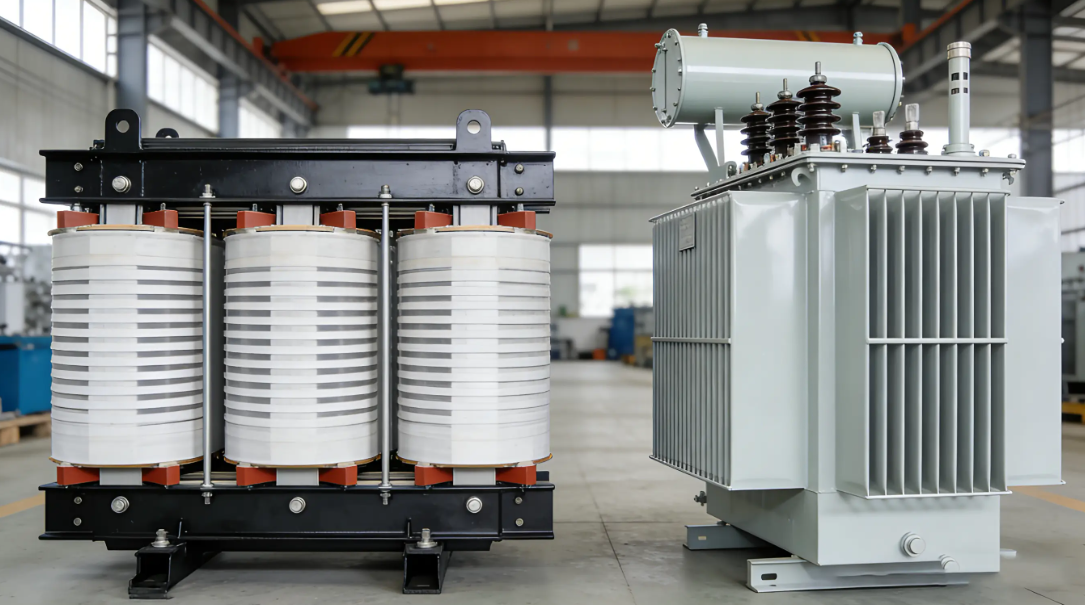
I. Introduction Among the core equipment in power systems, the safe and stable operation of transformers has always been a focal point of industry attention. As a central component of the transformer protection system, the parameter settings for temperature protection directly affect the service life of the equipment and the reliability of the power grid. This article will systematically analyze the core logic and specific parameters of temperature protection in light of the technical characteristics of dry-type and oil-immersed transformers, providing a professional reference for power industry professionals and technical enthusiasts.
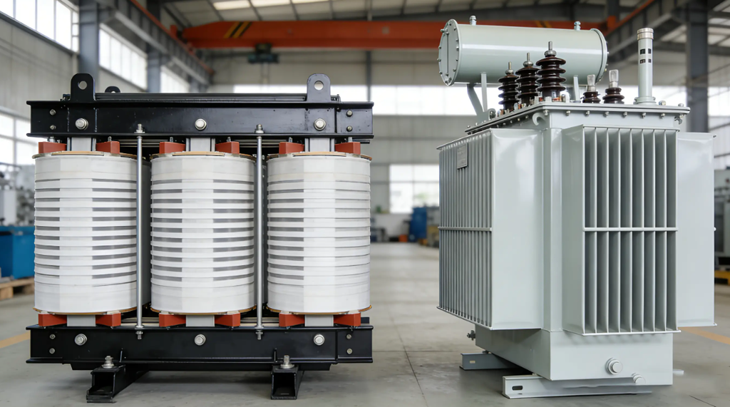
II. Dry-Type Transformers: Precise Protection Mechanisms in High-Temperature Environments Due to their flame-retardant and maintenance-free properties, dry-type transformers are widely used in urban distribution grids, high-rise buildings, and other applications. Their temperature protection settings are primarily based on the insulation class, with typical parameters shown in the table below:

Technical Logic Analysis:
Fan Control Logic: By setting a temperature differential control strategy of “95°C start / 75°C stop” (Class F), this approach not only prevents frequent fan start-stops from affecting equipment lifespan but also initiates forced cooling before the winding temperature approaches the critical threshold, ensuring the insulation system remains within a safe range.
Trip Threshold Setting: The trip temperature of 130°C (Class F) corresponds to the critical value for thermal aging of the insulation material. When the temperature exceeds this threshold, the insulation life of the windings will decline exponentially; an emergency trip serves as the last line of defense against thermal breakdown incidents.
Application Note: During actual operation, the alarm setpoint may be fine-tuned within a range of ±10°C based on load characteristics (such as the proportion of surge loads) and ventilation conditions; however, any adjustment to the trip threshold must be validated through an insulation life assessment.
III. Oil-immersed Transformers: Thermal Equilibrium Management
In the Oil Medium Oil-immersed transformers rely on the thermal conductivity of insulating oil for heat dissipation. Their temperature protection system is based on Class A insulation (maximum heat resistance of 105°C), and parameter settings place greater emphasis on the coupling relationship between oil temperature and winding temperature:
Upper oil layer temperature control: Cooling fans start at 65°C and stop at 55°C; an over-temperature alarm is triggered at 80°C, and the trip mechanism is activated at 90°C.
Temperature field characteristics: Winding temperatures are typically 10–15°C higher than the upper oil temperature; therefore, when the oil temperature reaches 90°C and the trip mechanism is activated, the winding temperature is already approaching the insulation limit of 105°C. This setting provides a safety margin to account for thermal conduction lag.
Key Technical Points:
1.Ambient Temperature Limits: National standards specify that the operating ambient temperature for transformers ranges from -25°C (outdoors) / -5°C (indoors) to 40°C; temperature rise correction calculations are required when operating outside this range.
2. Clarification of the Temperature Rise Concept: The “rated temperature rise” indicated on the nameplate refers to the maximum allowable heat generation of the transformer under standard ambient temperature (40°C). For example, if a dry-type transformer has a rated temperature rise of 100 K, its maximum operating temperature is 40°C + 100 K = 140°C (corresponding to Class H insulation).
3. Essence of Insulation Class: Insulation class does not refer to the electrical strength of the material but rather to thermal aging life standards determined based on the Arrhenius equation. Taking Class A insulation as an example, for every 8°C the temperature exceeds the limit value, the insulation life is halved; this is precisely the theoretical basis for setting temperature protection parameters.
IV. Key Recommendations for Operation
- Maintenance Regular Thermal Imaging Inspections: Analyze the temperature distribution of windings, bushings, and other components through infrared thermography to promptly identify potential hazards such as poor contacts and localized overheating.
- Oil Deterioration Early Warning: For oil-immersed transformers, establish a multidimensional early warning model by combining oil chromatographic analysis (e.g., dissolved gas content) with oil temperature data.
- Response to Extreme Operating Conditions: During periods of high load in summer, temporarily adjust the fan activation threshold (e.g., set to 90°C for Class F) and enhance the cleaning and maintenance of cooling systems (e.g., radiators).
V. Conclusion: The transformer temperature protection system serves as a critical safeguard for the reliability of power systems. Its parameter settings must not only adhere to the thermal aging characteristics of insulation materials but also be dynamically optimized based on specific application scenarios. Industry professionals should gain a deep understanding of the intrinsic relationship between “temperature rise, service life, and safety,” and achieve a balance between equipment safety and operational efficiency through refined operation and maintenance and intelligent monitoring.



Netia consequatur quaerat possimus voluptatibus aperiam. Possimus sunt unde dignissimos sunt reprehenderit laboriosam in